Flashing Tasmota onto Sonoff Basic
Hello!
I ordered a pack of 2 Sonoff Basic wi-fi switches as a first step into turning my home appliances into smart devices.
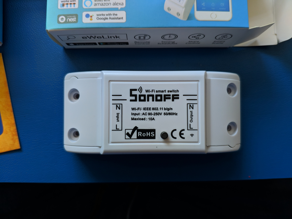
First thing I did was test them out using the stock Android app called EWELINK which is nice and full of options to customize the behavior of your connected appliance right out of the box.
However, I want to tinker with the device beyond what the manufacturer allows in stock mode, so in this (kind of) guide I will describe the steps I followed to successfully flash my switches with a custom firmware called Tasmota.
Preparing the hardware
I opened the device by running a plastic spudger along the edges of the case. It is held in place by 4 small clips which disengage very easily, even by using your fingernails. The board just comes off after separating both halves because nothing is holding it against the case.
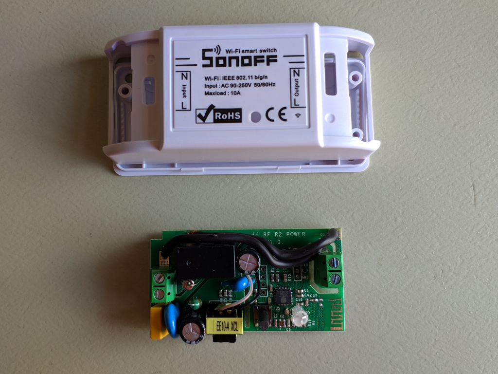
The board looks different from what most internet guides/video tutorials show. This seems to be a Sonoff RF R2 POWER V1.0
One of the noticeable changes is that solder traces are no longer used to carry the load’s power, instead they have been changed to cables which run along one of the edges.
Apparently the gauge of those cables is 12 AWG.
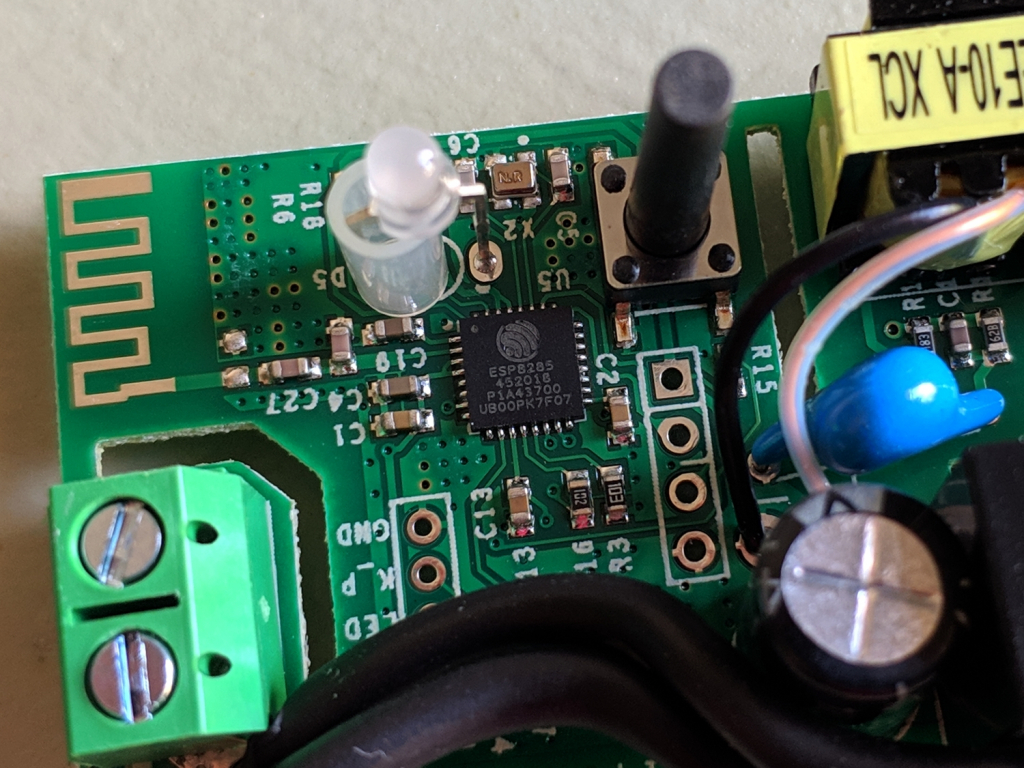
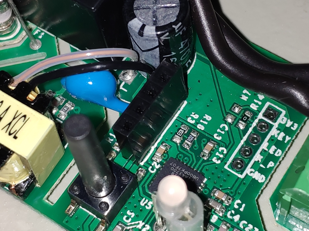
Luckily, they haven’t changed the fact it is based on a ESP8266 Wi-Fi module. As you can see, the chip being used is a ESP8285 which basically is an upgraded 8266 but with 1MB of FLASH memory.
What we are looking for are those 4 holes labeled GND-TX-RX-3V3 which will allow us to connect to the ESP chip and reflash it.
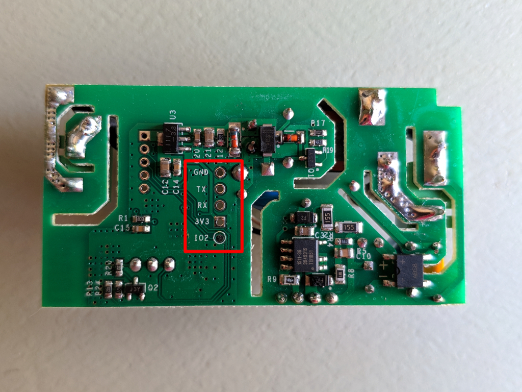
By using female pin headers (like those used in some Arduinos) we will get a solid connection to the board which will allow us to flash the chip as many times as we want with little effort.
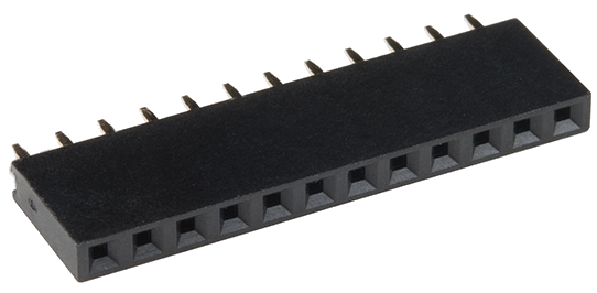
I wasn’t able to find 4-pin headers so I had to carefully cut each strip in 4-pin sections and then solder them into every device to be flashed.
After soldering it looks like this:
Flashing Tasmota
Let’s get into the actual flashing.
So, what is Tasmota and why would we use it?
Alternative firmware for ESP8266 based devices like iTead Sonoff with web UI, rules and timers, OTA updates, custom device templates and sensor support. Allows control over MQTT, HTTP, Serial and KNX for integrations with smart home systems. Written for Arduino IDE and PlatformIO.
As you can see, Tasmota adds many features which are not available while using the preloaded firmware like integrating the devices into existing home automation systems and the best part is that unlike flashing an ESP alone using Arduino IDE or other IDEs you can load the new firmware using tools designed specifically for this purpose which are very easy to use, no code-touching needed! (I like to touch code though 😉)
All the related documentation can be found in the project’s GitHub repo:
https://github.com/arendst/Sonoff-Tasmota
Since I don’t have an USB to serial converter at hand to connect to the Sonoff I will use an Arduino UNO I have lying around as a FTDI serial adapter instead .
We will be using Pyflasher to flash our custom firmware onto the ESP.
What about the software? where is it?
If you are not used to browsing GitHub then it can be a little hard to find the actual piece of software to flash into the device.
In the releases section the latest stable version of Tasmota can be found:
https://github.com/arendst/Sonoff-Tasmota/releases/
There’s a lot of binaries in each release, and picking the wrong one will result in errors while trying to flash the device. For most devices we should pick the sonoff.bin file.
After downloading and executing Pyflasher and having the .bin file then we can proceed to connect the Arduino to the Sonoff header we just soldered.
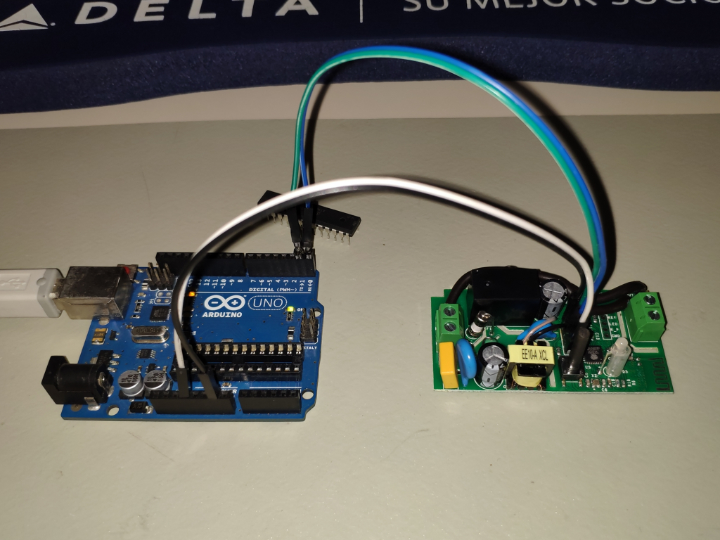
The wiring should go this way to work:
Arduino / Sonoff
GND – GND
(Digital Pin 1) TX – TX
(Digital Pin 0) RX – RX
3V – 3V3
On some sites they state that by connecting the RESET pin to GND should do the trick without removing the micro but it didn’t work for me. In my particular case I had to take the microcontroller off the main board of the Arduino to get it to work as a FTDI interface.
Before the flash process we need to put the ESP module on Bootloader mode.
With the device powered down, hold the GPIO 0 pin low by pressing the button and reconnecting the power, then release the button. Now the device is ready to be flashed.
1.- In Serial port look for the FTDI interface, in this case the Arduino is on COM5.
2.- Browse to where the sonoff.bin file resides.
3.- For the baud rate use 115200 as default speed.
4.- Flash mode: Dual Output (DOUT).
5.- For the Erase flash setting select the option to wipe all data.
6.- Finally, hit that Flash NodeMCU button.
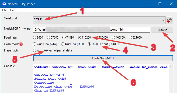
If everything goes as expected, you should see on the console that the recognized chip is an ESP8285 and flashing process should start afterwards.
Console output looks like this:
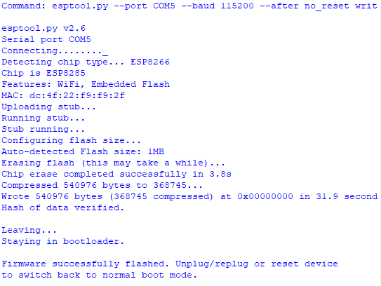
At this point the Sonoff is now loaded with Tasmota.
To access the configuration, connect device to power and press the button 4 times in a row to enable the AP mode.
Look for it with your smartphone or computer and the basic device configuration page should open:
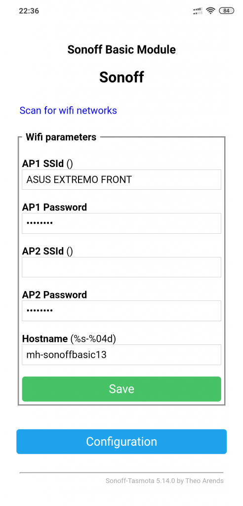
Set up your Wi-Fi network credentials as well as the hostname you want to use to connect to the device more easily.
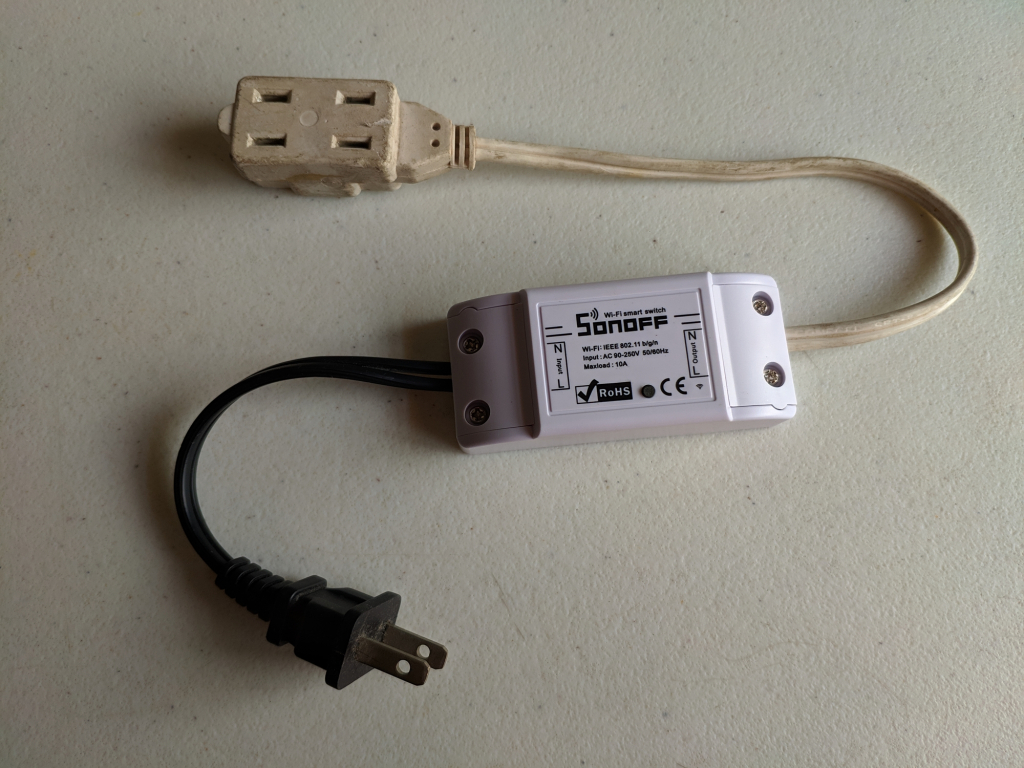
I used pieces of old extension cords to test the device, it works as expected heh
One thought on “Flashing Tasmota onto Sonoff Basic”
Nice blog!